Observatory Page - Kenthurst Observatory
Main menu:
- Home
- Blog
- Observatory
- Current Setup
- Current Images
- Original Setup
-
Original Images
- Meade LDX 10"
- Orion ED80
Observatory Page
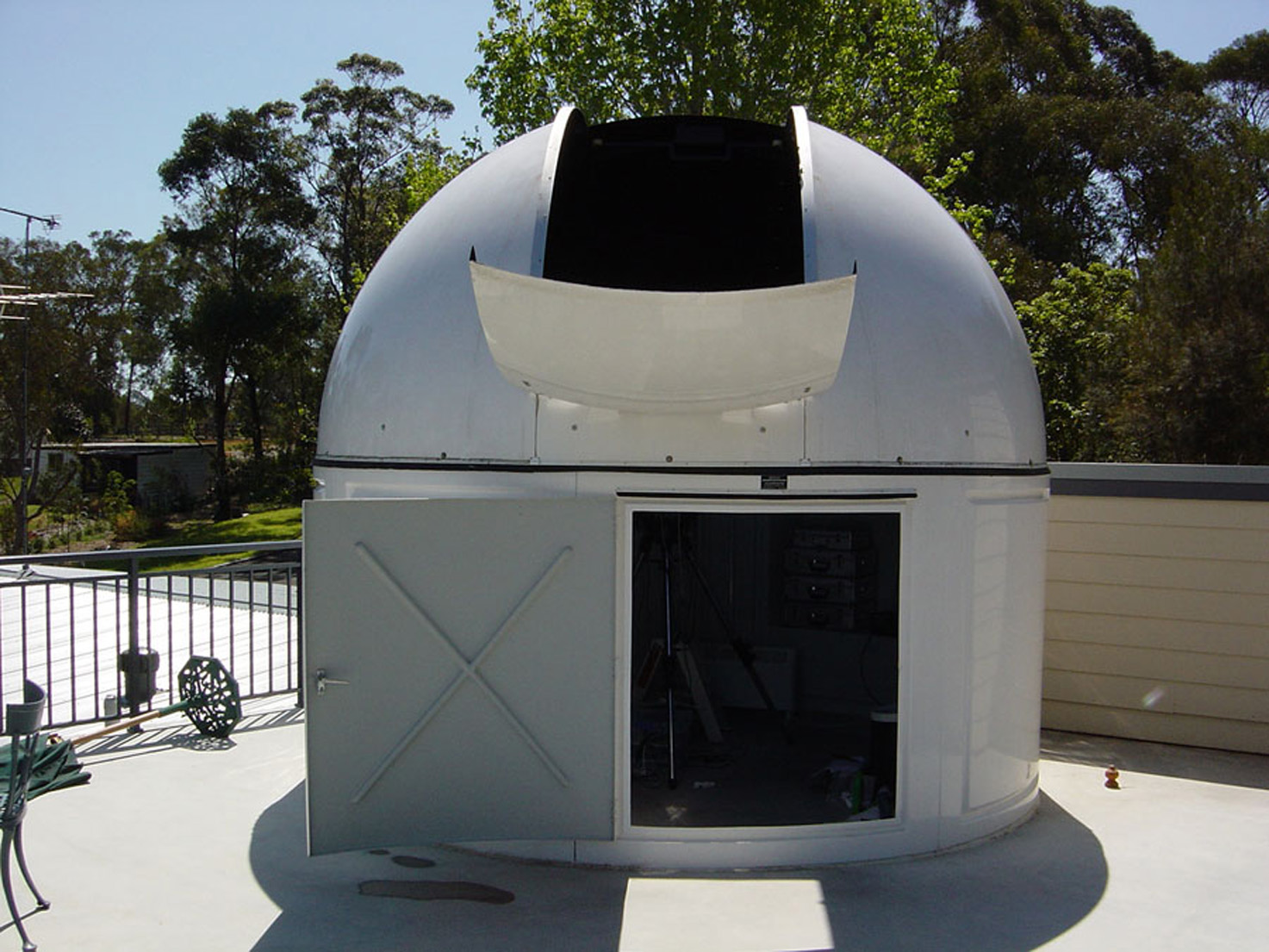
The observatory is a Sirius Observatories 3.5 metre diameter dome. It is located on a suspended slab built over a large family room. The slab is 170 mm thick reinforced concrete. An integral reinforced concrete beam runs across the width of the slab in order to provide a stable imaging platform. This arrangement has avoided the need to run a concrete pier from the telescope base down through the family room into the ground. Not visible is the upper shutter which has retracted back over the other side of the dome
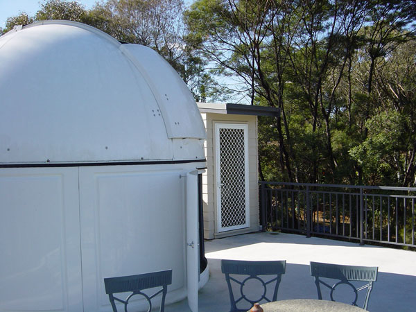
The image at left shows the doorway leading to steps down to the family room. In this view the dome's lower shutter is closed. The upper shutter is fully open, having rolled back over the rear side of the dome.
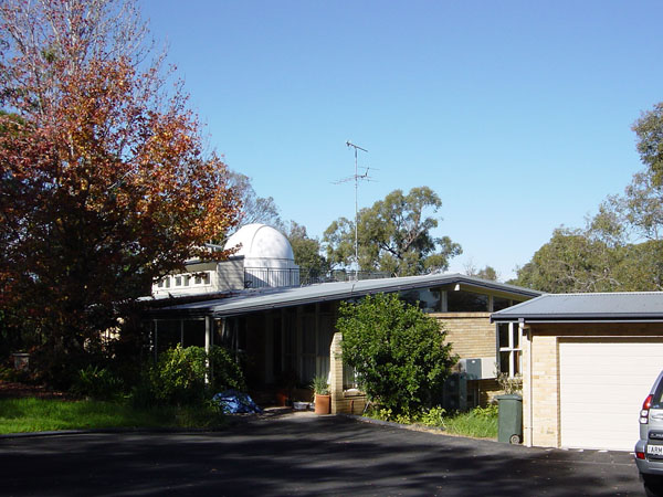
This is a view from the front drive. The structure on the roof to left of the dome is a light box. It allows light into the family room from the north during winter months.
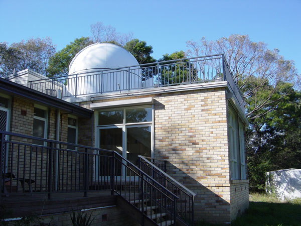
This is a view from the back garden. A water ring main and sprinklers can be seen running around the edge of the slab. It is fed by a petrol pump from the 33,000 litre concrete tank which is visible at bottom right. The large windows are also protected by motorised (manual override) shutters. These precautions are necessary because fires and high winds are common in the summer months.
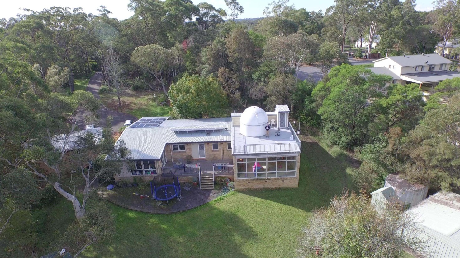
This is a recent view taken from a Phantom 3 drone. The house is located on a long, thin 2 hectare (5 acre) block surrounded by tall trees.
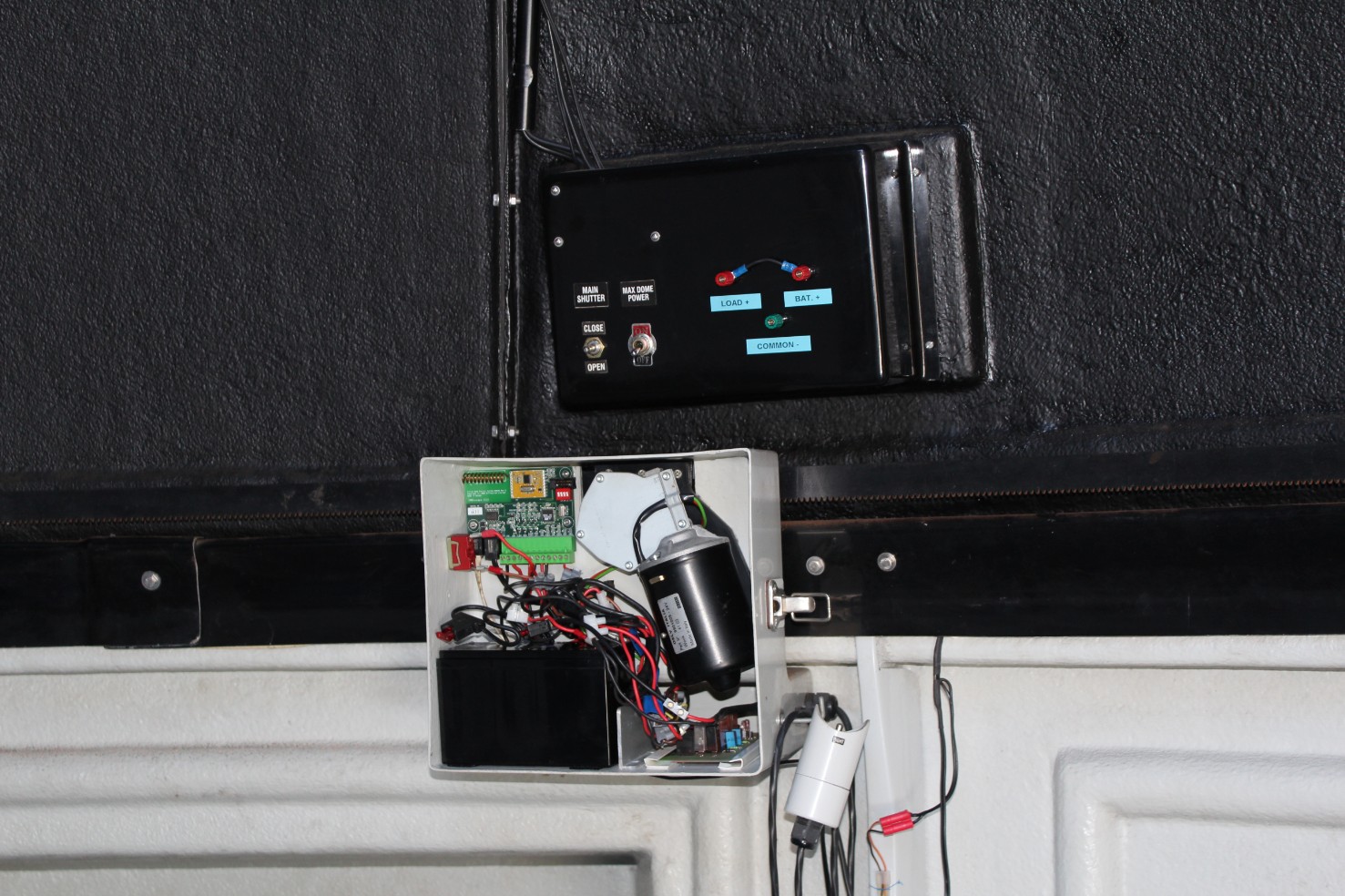
The black housing contains the battery and electronics which operate the upper dome shutter. A solar panel is located on the outside of the dome immediately behind the housing and charges a battery which provides power to open and close the two dome shutters. Extra terminals at right have been added to enable the upper dome battery to be charged externally, or to apply remote battery power to the upper shutter to close shutters in the event of failure of the primary battery.
The white box, with cover removed, contains the regular dome rotation battery, motor and electronics. The green printed circuit board at upper left is part of the MaxDome computerised dome automation system. An identical PCB is locaed in the black housing above. Communication betwee the two PCBs is by wireless. The motor drives the toothed bar which runs around the lower part of the upper dome. A second solar panel is on the outside behind the white box. The circuitry inside the box has been modified to allow the regular dome rotation battery to be isolated and the electrical circuitry to be powered by a larger external battery. This is further explained below.
The dome shutters and dome rotation can be controlled by computer or by manual override switches.
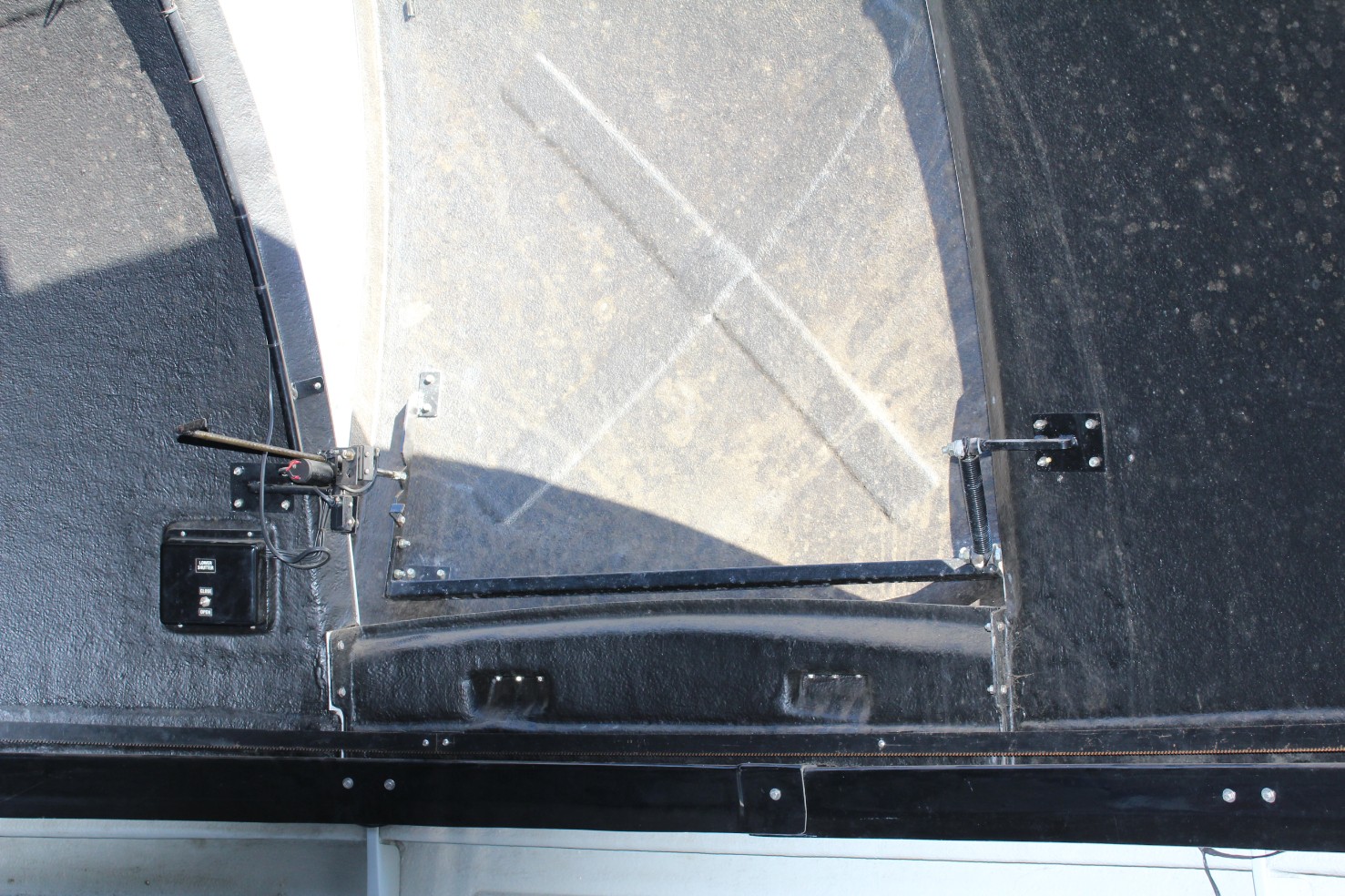
The above photo shows the lower shutter control and mechanical arrangement. Limit switches near the threaded rod switch off power to the shutter motor when the dome reaches a fully closed or fully open positonThe black housing contains circuitry to drive the motor and monitor the limit switches. An external shutter open/close toggle switch is visible.
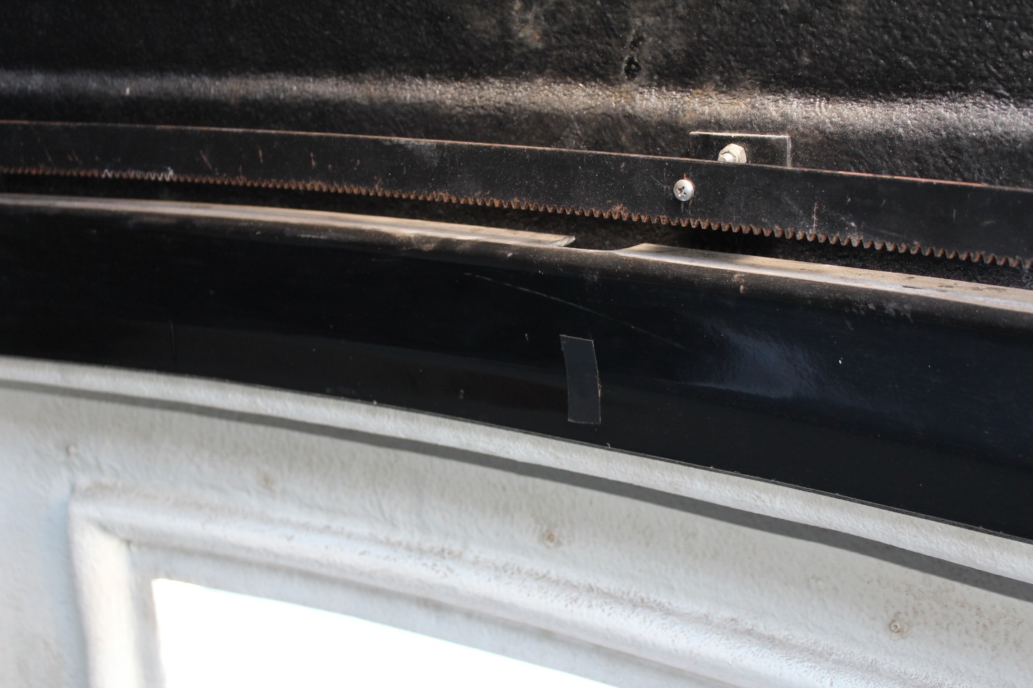
This photo shows the modification I made to allow the wheels attached to the upper, rotating portion of the dome to be tightened and even replaced if necessary. The black electrical tape covers a hole through which a screwdriver can be inserted to tighten the screw attaching a wheel. The cutout area above it provides space to remove and replace a wheel. Thus far, after ten years of operation no wheels have ever had to be adjusted or replaced.
The Boltwood Cloud Sensor monitors cloud cover, light/darkness, wind speed, relative humidity and dew point. It also detects rain. It is hard wired to the small electronics box shown in lower left of the photo below. The computer screen can provide a continuous display of these parameters plus user-

The Cloud Sensor electric control box has three connections. One is for low voltage D.C power from the A.C. plug-
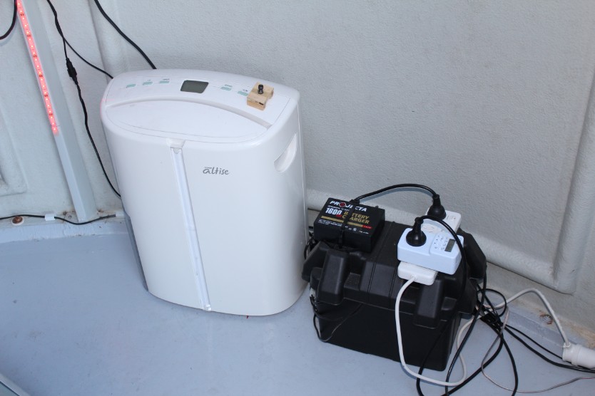
The dehumidifier is switched via the timer atop the battery to operate from 9-
The battery is switch connected to the lower dome rotation control box. It serves as a high capacity backup to the main battery therein. It also provides D.C. power to the four red LED strips (one of which is partially visible at left) which are equally spaced around the dome and to two white LED lighting strips. The illumination intensity of the red LEDs is variable. The white LED strips provide lighting when equipment needs to be adjusted or replaced.
Visible at left on the top of the battery is the battery's A.C. powered trickle charger.
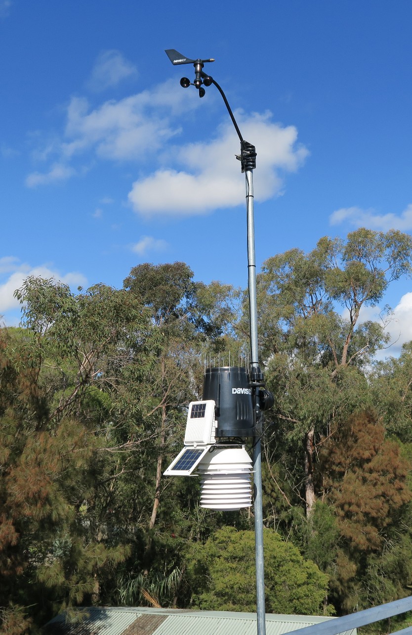
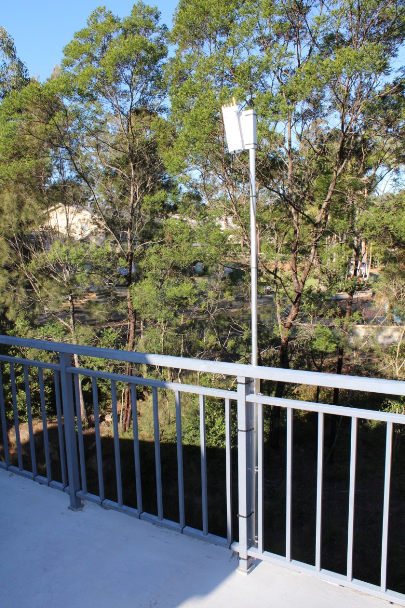
A recent addition is the Davis Weather Station, a Davis Wireless Vantage Pro2 Plus with fan-
This weather station gives more accurate readings than the Boltwood cloud sensor and is a better predictor of dew. It also has a data logger which runs 24 hours even when the dome equipment is unpowered. It however lacks a cloud sensor and does not have the sophisticated ability to close the dome under adverse weather conditions when there is a power failure.
Click on the image for the latest weather from the weather station.